I started designing a red light panel after seeing “What I’ve Learned’s” Youtube video on Red Light therapy.
The mechanics of how Red Light effects the mitochondria is that pumps in the mitochondria’s membrane are effected by certain wavelengths of light, and that either less gradient differences are required on either side of the membrane to activate the pumps that use the gradient difference for power, or that the pumps are effected directly and work more efficiently. In English: The upside is that ATP production is increased. Most published papers on the effect of different Red Light wavelengths and intensities comes from a research team from Russia.
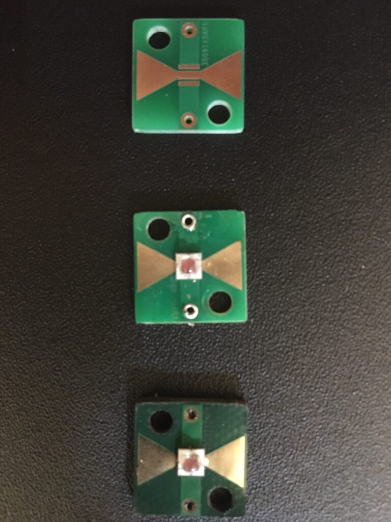
On the engineering side of things, the citation of a 660nm wavelength is very common, and so SST-20-DR LEDs were selected. I later discovered the Russian research does not support the wavelength specifically, but as part a bell curve range, 660nm not being optimal.
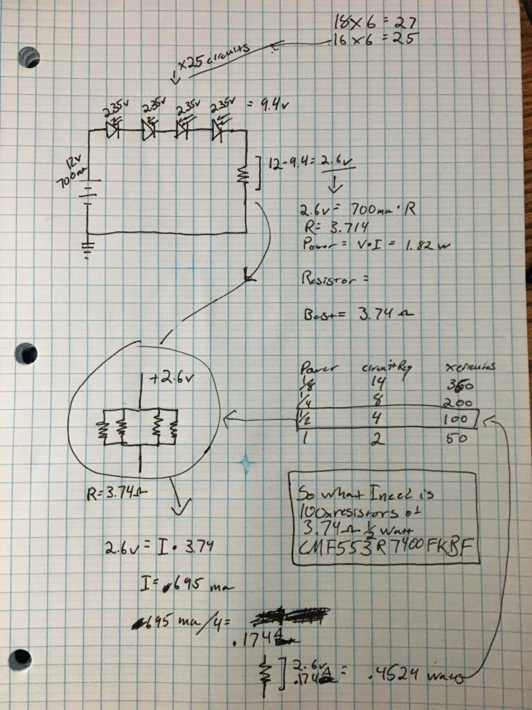
I wanted the intensity of the light to be the same as sunlight’s intensity at that wavelength in the morning hours, which wasn’t that difficult to calculate, although the further you move from the source of the light: the less intensity. There is a fair amount of geometry involved, with how much energy you want over a surface area to how far the diodes need to be apart from each other, and how far the panel needs to be from the target. After that it was testing the LEDs and their power requirements.
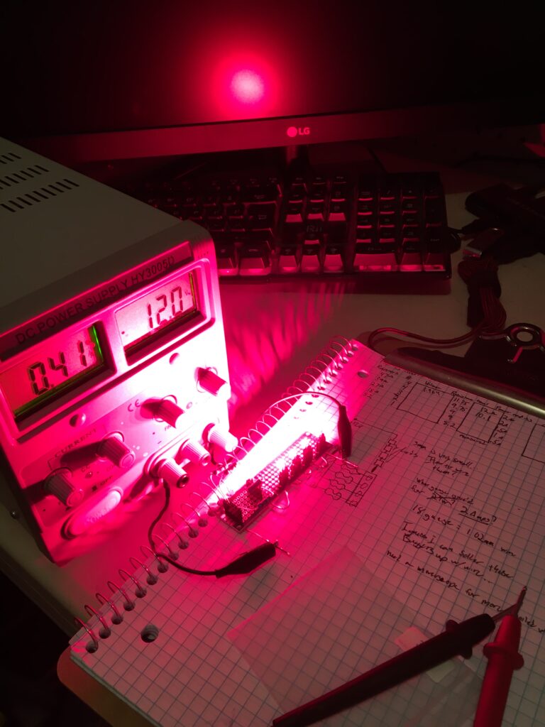
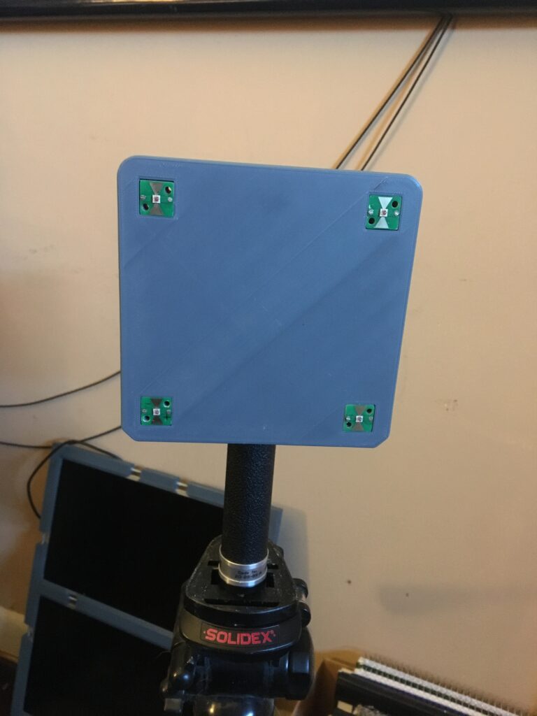
I designed and ordered the PCB boards that the LEDs would sit upon, and after constructing them with the Praxi reflow oven, I printed out the panel they would mount to. Unfortunately, several of the boards were non functional due to temperature issues in their construction, out of the 10 ordered, only 7 were usable. The panel in the picture was the original prototype, but I decided to build a smaller panel in light of fewer LEDs. Pun not intended.
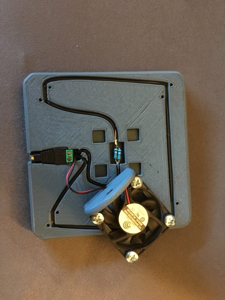
I also noticed the resistor bundle I opted for this prototype were rather hot, so I included a fan I could hook in parallel with the 12v power supply, as you can see in the images below.
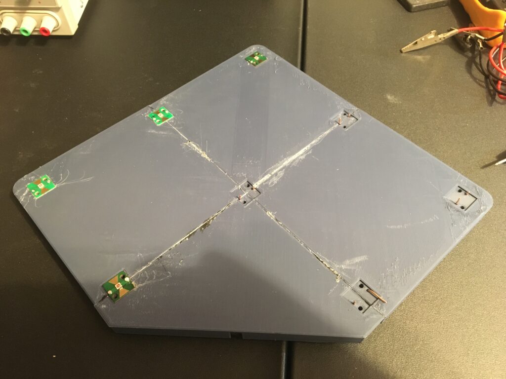
Eventually I settled on a single 3d printed panel. The LED boards are held well by the soldered wires that are inserted into recesses in the back. The fan mount doubles as a tripod mounting point, and is then glued into place. The power connector is press fit and holds well.
The results of the system is less than stellar however. Since there is no obvious effect health wise and due to the fact the 660nm is not optimal, I can’t judge if it actually works or not without prolonged study. However I have found the light panel useful when working with photosensitive resin, and if I ever return to photo development I am certain it will have use there as well.